To sign up to receive our emails, fill in the following fields and hit submit. Thanks, and welcome!
"*" indicates required fields
To sign up to receive our emails, fill in the following fields and hit submit. Thanks, and welcome!
"*" indicates required fields
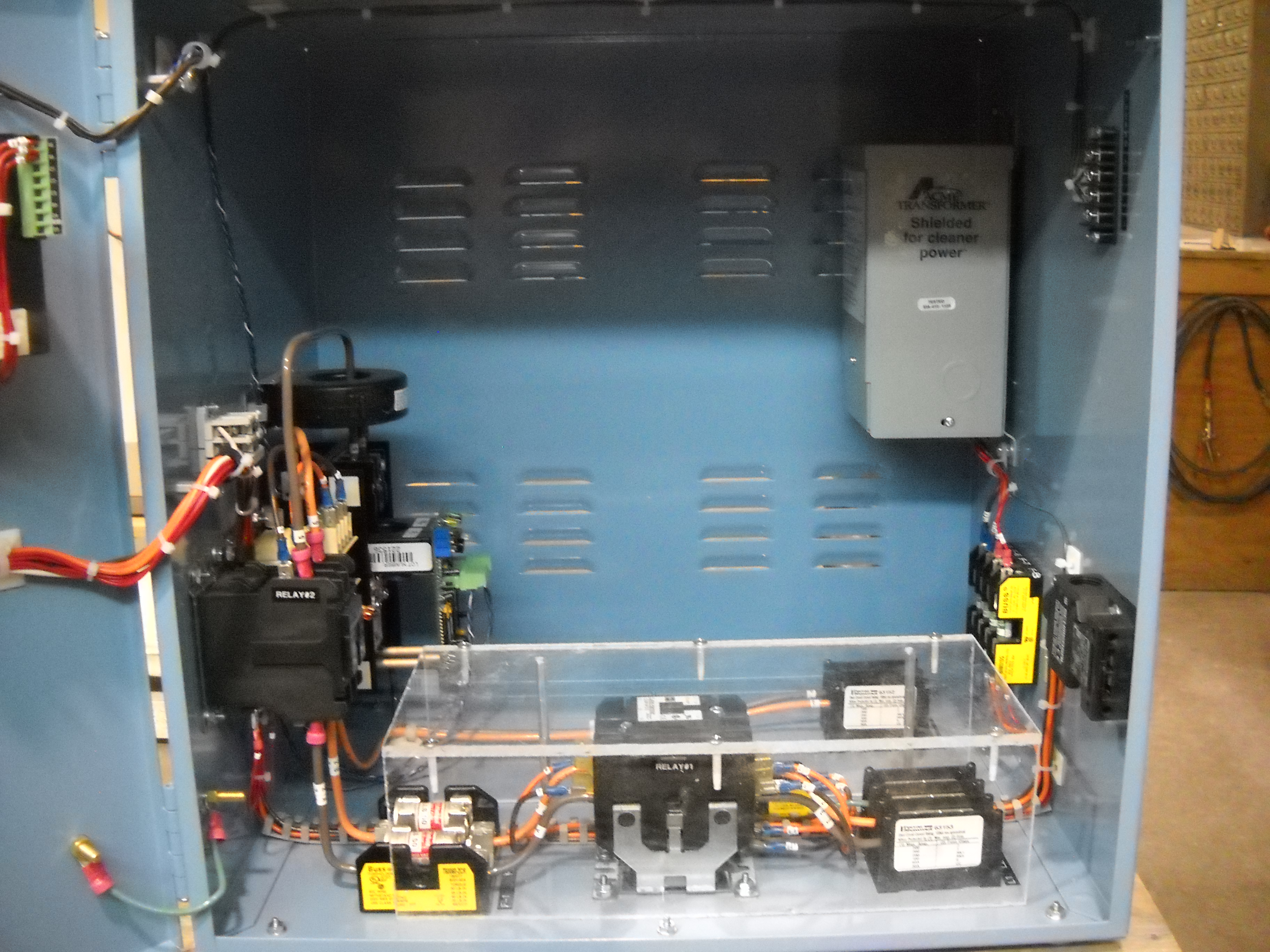
Components of a control system for a resistance heating system
Following is a brief introduction to how the main components of a Deltech Furnaces resistance heating system work together. The main components are the (1) control system, including the temperature controller and control thermocouple; power control system (including SCR power controller, current transformer, and ammeter); transformer; and overtemperature protection circuit (including a limit controller, contactor, and limit thermocouple); and (2) the heating elements. The essential function of the control system is to precisely regulate the amount of power going to the heating elements to ensure that the desired furnace temperature at any given time is attained and maintained within a very small margin of error.
The temperature controller – usually a Eurotherm 2404, Eurotherm 3504, or Yokogawa UP550 – follows a heating program entered by the furnace end user with the parameters required to melt/bisque/sinter a particular product. For example, suppose a program calls for the furnace to ramp to 1000 deg C at the rate of three deg per minute, and then hold (also called “soak”) for three hours, ramp down at the rate of one deg per minute to 600 deg C[1], and then end control. Once the furnace has completed the program “run”, the furnace is then allowed to cool to room temperature “at its own rate” as determined by furnace contents (load or no load), environmental temperature, etc.
If the temperature controller has event relays (“events”), the program can send instructions such as “open the vent flap” to the furnace electrical system which in turn activates the pneumatic cylinder which operates the flap. [2]
The program gives the temperature controller a task to accomplish, but it needs feedback to “know” whether or not it is doing its assigned job. For example, suppose the controller is following the first step (“segment”) in a program, and calling for the furnace to ramp to 1200 deg C in four hours. Suppose that two hours have elapsed. You would expect the furnace to be at  600 deg C at that point. But IS it?
Here comes the feedback. The temperature controller receives a continuous millivolt signal from the thermocouple. The number of millivolts corresponds to the actual furnace temperature, called the “process variable” (PV). For example, a type B thermocouple sending an 11.8mV signal is indicating a furnace temperature of 1650 deg C[3]. The temperature controller front panel readouts indicate two temperatures: the process variable and the “setpoint” (SP), which is the target temperature for the particular segment of the program which is operative at that point in time.
If the connection between the thermocouple and the temperature controller is broken for any reason (broken wire in the thermocouple, loose or faulty connection between the thermocouple extension wire and the thermocouple or the thermocouple input on the controller), the temperature controller readout will read “Sensor Break” or “Open” (or similar terminology depending upon the controller in use) and stop operating. That is, no power will be going to the elements because the controller will no longer be sending a signal to the power controller.
Based on its operating program and the information it is receiving from the thermocouple about the furnace temperature (see above), the temperature controller directs the SCR power controller to send from 0% to 100% of a maximum voltage to the transformer. It does this by sending a 4-20 mA signal where a 4mA signal directs the SCR to supply no power and a 20mA signal directs the SCR to supply full power.[4]
You may be familiar with the analogy between the flow of water and the flow of electricity. Voltage is like the pressure forcing water through a pipe. Amperage is like the continuous flow (current) of water going through the pipe. Resistance is like a closed valve preventing the water from flowing.
The function of the SCR is to control the amperage (current flow) going to the elements by controlling the voltage (pressure). One basic form of the power equation is I=E/R, where E=voltage, I=amperage, and R=resistance. For a given resistance level, lower voltage will result in lower amperage, and higher voltage in higher amperage. (Compare this with how a decrease/increase in water pressure increases/decreases the current flow when the size of the valve opening is held constant.)
Most Deltech resistance heating systems feature molydisilicide heating elements. To optimize element performance and life, Deltech carefully selects the parameters for voltage and amperage. When cold, molydisilicide heating elements have zero resistance, so applying full power would cause a dead short resulting in blown fuses and possibly damage to the elements. (In our water pipe analogy, zero resistance is the equivalent of having no valve in place to slow or stop the flow, so if the water pressure remains the same, the flow (current) will gush uncontrollably.) To prevent this, the SCR has a soft start” feature. It will send very low voltage and thus limited amperage to the transformer. (The low voltage is analogous to low water pressure. Without sufficient pressure, the flow of water (current) may slow to a trickle.)[5]
As the resistance increases with temperature, the voltage and amperage are regulated in such a way that the voltage to the elements is held constant, while the amperage is allowed to vary. Another formulation of the power equation is I=E/R. If the voltage is constant, then an increase in resistance will result in a decrease in amperage. (Imagine that the size of the valve opening in the water pipe has been reduced but the water pressure has been held constant. The flow (current) will slow because the impedance has been increased by the smaller size of the valve aperture.)
The transformer receives the voltage and resultant amperage from the SCR power controller, and then “transforms” the power, essentially inverting the voltage and amperage. The transformer primary receives the line voltage coming from the SCR. For example, suppose that the SCR output line is connected to the first of the transformer primary lugs, and it is identified as a 208V tap, and that the SCR is currently sending the full line voltage of 208V to the transformer primary. Suppose the transformer secondary has 50V and 60V lugs, and the line connecting the transformer secondary to the element power buss is connected to the 50V lug. Suppose the SCR is current limited at 40 amps. The 208V on the primary will be transformed to 50V on the secondary. 208V divided by 50V = 4.16 “turns”. So the original amperage will be increased by 4.16 times its original value. Thus the maximum amperage that can be obtained given the current limit of the SCR will be 40A x 4.16 or approximately 166A. Remember that lower amounts of voltage at the primary will result in lower voltage on the secondary. So for example 100V on the primary will still result in 50V on the secondary, so in this case the number of turns would be 2.0, and the amperage going to the elements would be at most 80A.
Many older model SCRs – most predominantly for our purposes, the Eurotherm 831 and 832 – had ammeters built in, so the SCRs were front panel mounted. Our current SCRs are located inside the cabinet, and the amperage is indicated on an ammeter in the cabinet door panel. The input to the ammeter is a 0-5 amp signal produced by the Current Transformer, which the ammeter then displays on 0-100 amp scale. [6]
As its name suggests, this feature of our control systems is designed to keep the furnace from heating to a temperature higher than its maximum allowable use termperature, resulting in damage or destruction of the furnace lining and heating elements. A “limit controller” – usually the West N6701 – sends a continuous signal to the “contactor”. If the signal ends, the contactor opens and current cannot flow.[7] The limit controller relay signal will end if the furnace reaches a temperature over the limit setpoint as indicated by its associated thermocouple), or if the thermocouple is broken or not connected properly (see thermocouple section above).
[1] Note that the furnace might not keep up with the programmed cooling rate: it can only be prevented from cooling too quickly.
[2] In the case of the Yokogawa, the events are programmed to stay on for a particular duration (e.g. 30 minutes). For the Eurotherms, the instruction will be in the form of an “event on” during a segment where the temperature is programmed to go from point A to point B at a particular ramp rate within a specified time period. For example, the segment might include a ramp from 500 deg C to 800 deg C at the rate of three degrees per minute, with the “event on” allowing the vent flap to open for a purpose such as getting rid of the fumes from binder burnout. Note however that for the Eurotherms the segment would not necessarily have to be programmed for a temperature change: the instruction might be to hold at the previous ramp temperature for a specified period of time and open the vent flap. Then another segment would be similarly programmed to hold the temperature and close the vent flap. For this purpose the segments could be short; e.g. one minute.
[3] See standard thermocouple reference tables for this data.
[4] The temperature controller can also be operated manually. That is, it can be placed in “Manual Mode”, and then the SCR can receive an instruction to call for a specified percentage of power.
[5]Thus when you initially apply power, you’ll see the ammeter display a low amperage which increases relatively quickly once the “soft start” feature is out of play. The amperage draw will depend on the 4-20mA signal being sent by the temperature controller, which in turn depends on the ramp rate of the operative segment of the program and the feedback from the thermocouple.
[6] Knowing the actual amperage draw of the system at a given time is useful in troubleshooting furnace problems. For example, a zero amperage reading for a furnace that is using a single set of elements in series could indicate a broken element. A 50% amperage reading (e.g. 20 amps when 40 is expected because, for example, the process variable is lagging behind the setpoint temperature) could indicate a broken element in a system using two sets of elements in series parallel. Current cannot flow through a broken circuit.resista
[7] Note that in most newer Deltech control systems, there are separate front panel switches for control and element power. This allows the temperature and limit controllers to continue to supply information about the system even when there is no power to the elements.


